It is nicer to have a larger opening, but at the same time it should be stronger than every other part of the dome, otherwise it will be the weak spot where the dome will collapse and fail, meanwhile all the strength of the other 99% of the pieces won't contribute to the strength of the dome. In particular, i have seen suggestions for modifying a hexagon (or pentagon) at the base by removing all the radial pieces in the center, or replacing them with some unstable geometry like a quadrilateral --- of course the dome will fail when those modifications fail.
My proposal is to modify the strut lengths (but not the geometry) of the minimal number of struts by the minimal amounts in order to enlarge one base triangle to a comfortable size. Specifically, you select a hexagon at the base with the highest central point (that is, the point where the 6 radial struts inside the hexagon come together) and "move" that central point upward by a couple of feet while keeping that point on the radius of the imaginary sphere that touches all the dome's vertices. This point should be moved just high enough to provide a big-enough entrance triangle but no higher, to avoid modifying the structure any more that necessary. (Note: i say select the hexagon at the base, but it might be possible for certain frequencies that there is a pentagon at the base with a higher central point than any of the hexagons. If that's the case, you would use that pentagon. On this page i refer to the hexagon because that's the right answer for the domes i've looked at.) Because of symmetry there will actually be several hexagons which could serve this purpose, you can of course pick any one of them.
I refer to the process of "moving" that vertex as "perturbing" in the rest of this page. To visualize this better, skip down to the pictures below.
Note that when this vertex is perturbed upward, the top 2 radial struts touching this vertex shrink in length, the middle 2 lengthen slightly, and the bottom 2 lengthen a lot. Lengthening the struts will weaken this part of the dome, unless you use stronger conduit. Since the rest of my domes are 3/4" EMT, i will be using 1" for the middle struts and 1 and 1/4" for the bottom ones. It's better to err on the side of overdoing this and make those four lengthening struts stronger than they need to be to completely avoid this being the weak spot in the dome.
Now the tricky question is what the new lengths of these 6 struts are. The rest of this page answers that question.
Note that the apex of the enlarged triangle is at the height found by multiplying the dome radius by the cosine of the angle theta of that perturbed point. Specifically, theta is the angular declination from the top of the dome, and is the same standard theta as in the usual polar coordinate system. In the tables below i refer to the cosine of theta as the entrance apex factor, so that you can easily mutiply it by the dome radius to get some idea whether the opening is big enough.
When DOME creates output for POV-Ray, it does so with two files: a top-level file named myfile.pov (whatever name you told it to use) which actually just contains globals about the colors and view, then includes a second file which is always named DOME.INC which contains the actual geometry. I didn't like the default view globals in the myfile.pov file so i made my own which was used to render the pictures below.
Example command lines for the modified DOME software are:
dome -f2 -s -z-0.001 -v mydome.pov
dome -f2 -s -z-0.001 -qft58.2825 -qfp36 -qtt40 -qtp36 mydome.pov
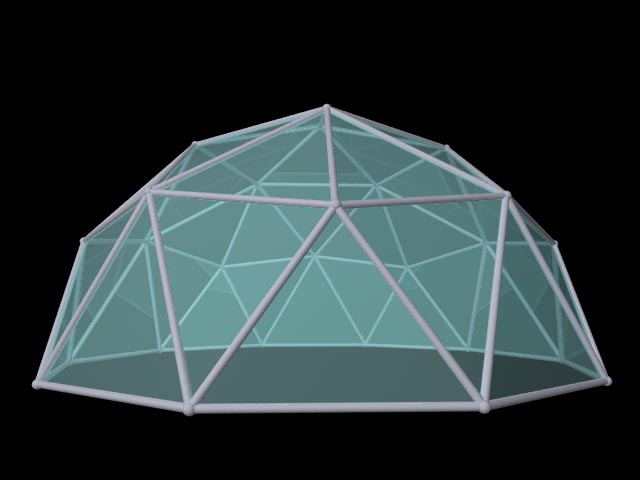
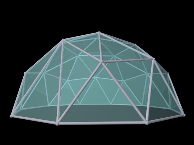
I only tried theta = 40 and 45 degrees because for my 8.372-foot radius dome, \ theta = 40 provided an entrance apex of 8.372 times 0.766, or 6.41 feet which seems adequate. That is, i chose the theta = 40 line of the table below. Here are the strut ratios found for that value of theta = 40 and 45 (and the original unmodified for comparison).
| theta in degrees | entrance apex factor = cosine(theta) | Top 2 struts' strut ratio | Middle 2 struts' strut ratio | Bottom 2 struts' strut ratio |
| 58.2825 (original) | 0.5257 | 0.6180 | 0.5465 | 0.6180 |
| 45 | 0.7071 | 0.4422 | 0.5867 | 0.8093 |
| 40 | 0.7660 | 0.3872 | 0.6201 | 0.8817 |
Here are POV-Ray renderings of the original and modified geometry. Click for larger pictures.
I refer here to the modified struts partly using the letter code for the strut each replaces, for clarity. It's also a good idea to mark these struts the same way as the ones they replace (consistent color coding, for example) to eliminate confusion at assembly time.
Example command lines for the modified DOME software are:
dome -f4 -s -z-0.001 -v mydome.pov
dome -f4 -s -z-0.001 -qft73.9549 -qfp26.2677 -qtt66 -qtp26.2677 mydome.pov
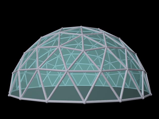
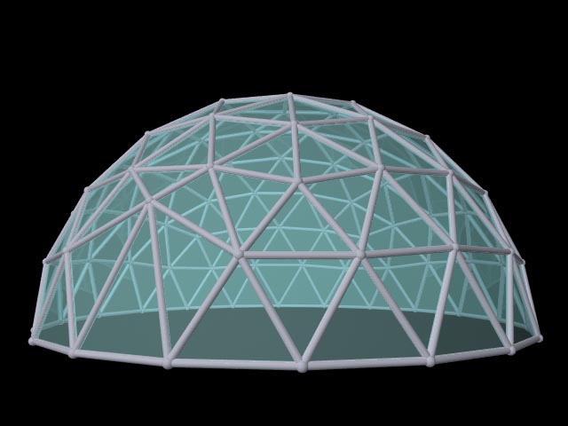
I only tried theta = 66 degrees because for my 16.033-foot radius dome that provided an entrance apex of 16.033 times 0.4067, or 6.52 feet which seems adequate. Here are the strut ratios found for that value of theta (and the original unmodified for comparison).
| theta in degrees | entrance apex factor = cosine(theta) | Top C strut ratio | Top D strut ratio | Middle C strut ratio | Middle E strut ratio | Bottom D strut ratio | Bottom E strut ratio |
| 73.9549 (original) | 0.2764 | 0.2945 | 0.3129 | 0.2945 | 0.3249 | 0.3129 | 0.3249 |
| 66 | 0.4067 | 0.1914 | 0.2012 | 0.3301 | 0.3458 | 0.4381 | 0.4463 |
Here are POV-Ray renderings of the original and modified geometry. Click for larger pictures.
Note that the code i added only really works for POV output in sphere (-s) mode, which is probably how you want to use it anyway. Here are the changes i made:
If you want to modify and rebuild the code on windows, you can use cygwin with the included makefile. In fact the build in the zip file i made depends on some of the cygwin DLLs so you'll need it anyway unless you want to rebuild the source some other way.